 Add Beam ( Modeling > F2 >
  Structural Steel > select " Beam ")
Tool summary :
- Adds a beam to the 3D model. Locate two points and make entries on the Beam Edit window to define the beam.
- The points you locate define the workline of the beam, which will be drawn along the center of the top flange of the beam.
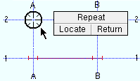
- After you have added one beam, you can add another beam with the same settings using middle-click ( Repeat ) while the point-location target (
 ) is where you want the to-be-added beam's left-end work point.
- You may, before you begin this operation, find that there is a beam in your 3D model that you want to duplicate. To get a near duplicate of that beam, double-click its main material and press " OK " on its edit window without changing anything. Then invoke Add Beam and locate the two points of the duplicate beam. To get a duplicate beam that is the exact length of the original, you can -- instead of locating two points -- middle-click ( Repeat ) while the point-location target ( ) is where you want the to-be-added beam's left-end work point.
- See (on this page):
Also see :
- Beam (index)
- Beam Edit window (opens with Add Beam unless you show the options bar)
- Show member add options bar ( User and Site Options > Modeling > ) (
 )
)
- Automatically process after modeling operation ( User and Site Options > Modeling > )
- Member component items to copy/repeat ( User and Site Options > Site " > , affects Repeat )
- Member status items to copy/repeat ( User and Site Options > Site , affects Repeat )
- How left end relates to work point coordinates (topic)
- Member Copy (alternative to Add Beam )
- Edit Member (various ways to edit a beam)
- Select a beam, right-click (Menu) , choose " Edit " (one way to edit a beam)
- "Edit Other" to edit all members under one mark (highly recommended)
- Move/Stretch Members (to move/stretch beams
- Move/Stretch Members, Include Material (same as Move/Stretch Members , but often better)
- Erase Member (undoes Add Beam )
- Work point not at center of column (connection failure message)
- Constructing the 3D Model (topic)
- Offset Controls (affects Add Beam )
page 1 | contents | F2 > structural steel > beam | top
 Videos :
|
|
|
page 1 | contents | F2 > structural steel > beam | top
Quick instructions (also see the detailed instructions ) :
|
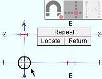
1 . Invoke Add Beam , then left-click ( Locate ) when the target ( |
|
2 . Left-click ( Locate ) when the point location target ( |
|
3 . On the Beam Edit window, enter the settings for the beam, then press " OK ." |
|
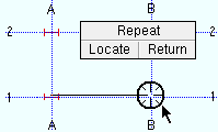
4 . The new beam appears. Right-click ( Return ) if you are done adding beams. Or you can left-click ( Locate ) or middle-click ( Repeat ) if you want to add another beam. |
page 1 | contents | F2 > structural steel > beam | top
Detailed instructions (also see the quick instructions ) :
The following instructions assume that you are using a 3-button mouse.
1 . Before adding a beam:
1a : Open a plan view that is at the elevation of the top flanges of the to-be-added beams. Non sloping beams are easiest to add one floor at a time, using plan views of each floor. To input a sloping beam, you may wish to open an elevation view , but you can also add sloping beams in a plan view, for example, by adjusting the " End elevation " of the beam on its edit window in step 4, or by selecting appropriate Locators when you locate the beam's work points.
1b : Lay out grid lines or construction lines so that there are points of intersection ( INCL points) wherever you want to place the work points of the beam(s) you are adding. It's a good idea to reference the elevation (Z coordinate) reported on the X-Y-Z display while locating beam work points.
1c : Optionally set the toolbar icon or set User and Site Options > Modeling > " Automatically process after modeling operation " to a choice that will cause the beam you are adding to automatically have solids created and piecemarks applied when you press " OK " to close the Beam Edit window that opens in step 4.
Note: If you locate work points using INCL with Offset Controls set to offsets of zero, the top flange of the beam is at the elevation of the plan view you are in.
2 . Invoke Add Beam using any one (1) of the following methods:
- Right-click ( Menu ) and choose Add Member > Structural Steel > Beam .
- On your ribbon, click the Add Beam icon, which is pictured above. If the icon is not currently on your ribbon, you can add it using the Ribbon Editor . In the Ribbon Editor , choose Model -- Member > Add Beam . The " Add Beam " icon can also be found in the " Drawer of Add Tools ."
- Use a keyboard shortcut (for example, F2 ). Add Beam is in the keyboard configuration " Command group " called ' Model -- Member '.
- With Member Mode mouse bindings active, middle-click ( Add ). On the selection dialog that opens, double-click " Beam. "
- You can also add the tool to a mode of your choice. In Mode Configuration , the tool can be selected from the " Command group " called ' Model -- Member '.
3 . Locate - Repeat - Return mouse bindings become active, and you are prompted to locate the beam's work points. To get an automatic beam-to-beam connection, the beam must go to a plane through the workline of the other beam. The two worklines do not have to be at the same elevation. A beam can be offset from the workline of a column, but must be on the column. You are not permitted to lay out a perfectly vertical beam. Do the following to locate the beam's two work points.
|
|
|
bindings |
3a : Select a Locate option (e.g. INCL ), then move your mouse pointer (
) so that the point location target (
3b : The status line prompts, " Locate second point: " Position the point location target (
Tip 1: Together the two points you just added define the workline of the beam. Beam worklines (stick form member lines) are drawn across the top flange of a wide flange or S shape or welded plate wide flange or welded plate box or HSS/TS beam. For a channel beam, the workline is along the heel of the top flange of the channel.
Tip 2: The Locate option INCM (intersection of a construction line and member) is an excellent choice for framing an intermediate beam between two sloping beams in a plan view.
Tip 3: The Locate option EXPT (exact point) selects a work point at the end of a member. If, for example, you want the top flange of a beam to line up with the top of a column, EXPT is an excellent choice.
Tip 4: The Locate option DXDY is an excellent choice for laying out the work points of a sloping beam in a plan view.
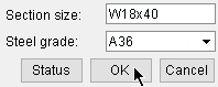
4 . The Beam Edit window opens. On it are the settings of the beam whose work points you located in step 3. Since process on the fly takes place even before the window opens, connection design automatically sets back the beam you have added from the center of the beam/column you are framing to so that the members do not overlap and appropriate field clearances are applied. Also, all relevant connection design locks are available to you immediately when the window opens, and process on the fly will continuously update connection design locks as you make changes on the edit window.
Alternative 1 : Edit the settings as desired (see the notes below), then press the " OK " button. Go to step 5.
Alternative 2 : Press the Cancel button to close this window and go back to step 3.
Note 1: Many of the settings on the Beam Edit window apply to the ends of the beam, rather than the beam as a whole. You must enter settings for the left end and the right end of the beam separately.
Note 2: The default settings on this window are those of the last beam you added or edited in this session of Modeling . Even if all you do is double-click a beam and press " OK " on its edit window, that beam's settings become the defaults for the next-added beam (exception: see " Swap member ends "). You therefore only have to make changes to those settings which are different for the newly added beam.
Note 3: " Copy " (
), " Paste " (
), " Save " (
) and " Load " (
) buttons let you quickly apply or save settings under particular sections on the Beam Edit window. The set of these buttons at the top of the window applies to the entire window. The set of these buttons under the " Left end settings " or " Right end settings " are for connections. You can even copy and paste settings to opposite ends on this same window.
Note 4: Wherever possible, it is recommended that you apply auto standard connections to the ends of beams. This ensures that similar connections are designed for similar beams in similar framing situations. You can also apply user defined connections and "
Moment " connections on the Beam Edit window.
Note 5: Certain beam settings pertain to the physical geometry of the beam. For instance, " Section size ," " Web rotation ," " End elevation ." To get a proper system connection on the end of a beam, be sure that these options are filled out with the settings the you want.
5 . The work line of the beam you just added shows up on screen in stick form . If User and Site Options > Modeling > " Automatically process after modeling operation " is ' Process and create solids ', the new beam will have automatically undergone all phases of Process and Create Solids . If that option is ' Process ' or ' Do nothing ', then you will have to Process > Process and Create Solids in order to have the member piecemarked and able to be displayed in a solid form . Do one (1) of the following:
|
|
|
bindings |
Alternative 1 : Move the mouse pointer (
Alternative 2 : Follow these instructions beginning with step 3 to add a beam with different settings than the one you just laid out.
Alternative 3 : Right-click ( Return ) if you are done laying out beams.
page 1 | contents | F2 > structural steel > beam | top
Adding beams using the options bar (classic) :
|
|
User and Site Options > Modeling > " Show member add options bar " can be set to ' Disabled ' or ' Top ' or ' Bottom '. When ' Top ' or ' Bottom ' is selected, extra space is allocated on your top or bottom toolbar to provide feedback and options related to the adding of a beam, column or brace. When you choose Model > Member > Add > Beam or invoke Add Beam using any other method , the options bar is activated, allowing you to quickly add beams without having to open the Beam Edit window. Note in the following example that the left " End elevation " and right " End elevation " are locked ( ![]() ), which results in the elevation of the member ends being determined by the entered values. Also, the entry made to " User defined connection " is valid due to the " Input connection type " being set to ' User defined '.
), which results in the elevation of the member ends being determined by the entered values. Also, the entry made to " User defined connection " is valid due to the " Input connection type " being set to ' User defined '.
![]()
The " Continuous add mode " button (
or
) stops and starts continuous mode. Beams added using continuous mode are end-to-end, with the second point of a being-added beam the same as the first point of the next-added beam. Continuous mode requires the location of fewer points than the two clicks (one for each end) that are required for a beam added in non-continuous mode. You need to turn continuous mode off before you can add a beam that is not end-to-end with the previously added beam.
The " Launch member edit " button (
or
) stops and starts the opening of the Beam Edit window with each beam that is added. The normal default that is applied to the first member added in a Modeling session is to not open the member's edit window. If you want the window to open, click the icon before you locate a point to add a beam. The window opens for each beam that is subsequently added during your current Modeling session until you click the icon again or restart Modeling .